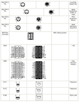
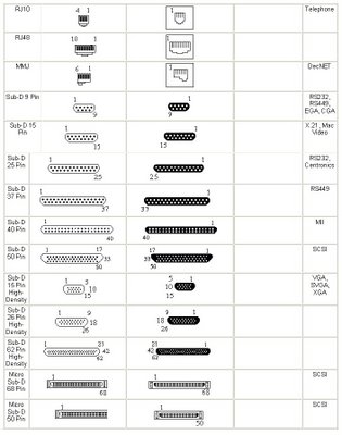
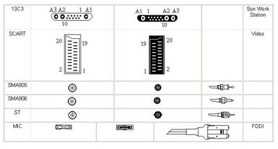
Excerpt and modified from various sites related to this topic (e.g. NetworkCablesOnlin.com, etc.)
What is Network Cabling?
Cable is the medium through which information usually moves from one network device to another. There are several types of cable which are commonly used with LANs. In some cases, a network will utilize only one type of cable, other networks will use a variety of cable types. The type of cable chosen for a network is related to the network's topology, protocol, and size. Understanding the characteristics of different types of cable and how they relate to other aspects of a network is necessary for the development of a successful network.
The following sections discuss the types of cables used in networks and other related topics.
· Unshielded Twisted Pair (UTP) Cable
· Shielded Twisted Pair (STP) Cable
· Coaxial Cable
· Fiber Optic Cable
· Wireless LANs
· Cable Installation Guides
Unshielded Twisted Pair (UTP) Cable
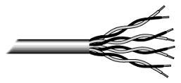
Twisted pair cabling comes in two varieties: shielded and unshielded. Unshielded twisted pair (UTP) is the most popular and is generally the best option for school networks (See fig. 1).
Fig.1. Unshielded twisted pair
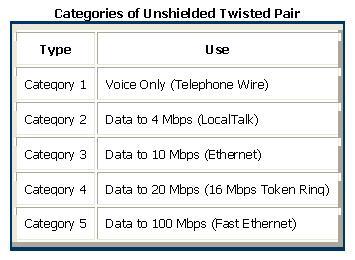
The quality of UTP may vary from telephone-grade wire to extremely high-speed cable. The cable has four pairs of wires inside the jacket. Each pair is twisted with a different number of twists per inch to help eliminate interference from adjacent pairs and other electrical devices. The tighter the twisting, the higher the supported transmission rate and the greater the cost per foot. The EIA/TIA (Electronic Industry Association/Telecommunication Industry Association) has established standards of UTP and rated five categories of wire.
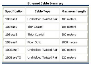
Buy the best cable you can afford; most schools purchase Category 3 or Category 5. If you are designing a 10 Mbps Ethernet network and are considering the cost savings of buying Category 3 wire instead of Category 5, remember that the Category 5 cable will provide more "room to grow" as transmission technologies increase. Both Category 3 and Category 5 UTP have a maximum segment length of 100 meters. In Florida, Category 5 cable is required for retrofit grants. 10BaseT refers to the specifications for unshielded twisted pair cable (Category 3, 4, or 5) carrying Ethernet signals. Category 6 is relatively new and is used for gigabit connections.
Unshielded Twisted Pair Connector
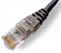
The standard connector for unshielded twisted pair cabling is an RJ-45 connector. This is a plastic connector that looks like a large telephone-style connector (See fig. 2). A slot allows the RJ-45 to be inserted only one way. RJ stands for Registered Jack, implying that the connector follows a standard borrowed from the telephone industry. This standard designates which wire goes with each pin inside the connector.
Fig. 2. RJ-45 connector
Shielded Twisted Pair (STP) Cable
A disadvantage of UTP is that it may be susceptible to radio and electrical frequency interference. Shielded twisted pair (STP) is suitable for environments with electrical interference; however, the extra shielding can make the cables quite bulky. Shielded twisted pair is often used on networks using Token Ring topology.
Coaxial Cable
Coaxial cabling has a single copper conductor at its center. A plastic layer provides insulation between the center conductor and a braided metal shield (See fig. 3). The metal shield helps to block any outside interference from fluorescent lights, motors, and other computers.
Fig. 3. Coaxial cable
Although coaxial cabling is difficult to install, it is highly resistant to signal interference. In addition, it can support greater cable lengths between network devices than twisted pair cable. The two types of coaxial cabling are thick coaxial and thin coaxial.
Thin coaxial cable is also referred to as thinnet. 10Base2 refers to the specifications for thin coaxial cable carrying Ethernet signals. The 2 refers to the approximate maximum segment length being 200 meters. In actual fact the maximum segment length is 185 meters. Thin coaxial cable is popular in school networks, especially linear bus networks.
Thick coaxial cable is also referred to as thicknet. 10Base5 refers to the specifications for thick coaxial cable carrying Ethernet signals. The 5 refers to the maximum segment length being 500 meters. Thick coaxial cable has an extra protective plastic cover that helps keep moisture away from the center conductor. This makes thick coaxial a great choice when running longer lengths in a linear bus network. One disadvantage of thick coaxial is that it does not bend easily and is difficult to install.
Coaxial Cable ConnectorsThe most common type of connector used with coaxial cables is the Bayone-Neill-Concelman (BNC) connector (See fig. 4). Different types of adapters are available for BNC connectors, including a T-connector, barrel connector, and terminator. Connectors on the cable are the weakest points in any network. To help avoid problems with your network, always use the BNC connectors that crimp, rather than screw, onto the cable.
Fig. 4. BNC connector
Fiber Optic Cable
Fiber optic cabling consists of a center glass core surrounded by several layers of protective materials (See fig. 5). It transmits light rather than electronic signals eliminating the problem of electrical interference. This makes it ideal for certain environments that contain a large amount of electrical interference. It has also made it the standard for connecting networks between buildings, due to its immunity to the effects of moisture and lighting.
Fiber optic cable has the ability to transmit signals over much longer distances than coaxial and twisted pair. It also has the capability to carry information at vastly greater speeds. This capacity broadens communication possibilities to include services such as video conferencing and interactive services. The cost of fiber optic cabling is comparable to copper cabling; however, it is more difficult to install and modify. 10BaseF refers to the specifications for fiber optic cable carrying Ethernet signals.
Fig.5. Fiber optic cable
Facts about fiber optic cables:
· Outer insulating jacket is made of Teflon or PVC.
· Kevlar fiber helps to strengthen the cable and prevent breakage.
· A plastic coating is used to cushion the fiber center.
· Center (core) is made of glass or plastic fibers.
Fiber Optic Connector
The most common connector used with fiber optic cable is an ST connector. It is barrel shaped, similar to a BNC connector. A newer connector, the SC, is becoming more popular. It has a squared face and is easier to connect in a confined space.
Wireless LANs
Not all networks are connected with cabling; some networks are wireless. Wireless LANs use high frequency radio signals, infrared light beams, or lasers to communicate between the workstations and the file server or hubs. Each workstation and file server on a wireless network has some sort of transceiver/antenna to send and receive the data. Information is relayed between transceivers as if they were physically connected. For longer distance, wireless communications can also take place through cellular telephone technology, microwave transmission, or by satellite.
Wireless networks are great for allowing laptop computers or remote computers to connect to the LAN. Wireless networks are also beneficial in older buildings where it may be difficult or impossible to install cables.
The two most common types of infrared communications used in schools are line-of-sight and scattered broadcast. Line-of-sight communication means that there must be an unblocked direct line between the workstation and the transceiver. If a person walks within the line-of-sight while there is a transmission, the information would need to be sent again. This kind of obstruction can slow down the wireless network.
Scattered infrared communication is a broadcast of infrared transmissions sent out in multiple directions that bounces off walls and ceilings until it eventually hits the receiver. Networking communications with laser are virtually the same as line-of-sight infrared networks.
Wireless LANs have several disadvantages. They provide poor security, and are susceptible to interference from lights and electronic devices. They are also slower than LANs using cabling.
Installing Cable - Some Guidelines
When running cable, it is best to follow a few simple rules:
· Always use more cable than you need. Leave plenty of slack.
· Test every part of a network as you install it. Even if it is brand new, it may have problems that will be difficult to isolate later.
· Stay at least 3 feet away from fluorescent light boxes and other sources of electrical interference.
· If it is necessary to run cable across the floor, cover the cable with cable protectors.
· Label both ends of each cable.
· Use cable ties (not tape) to keep cables in the same location together.
Common Questions:
Question. Which cable should I choose?
Answers.
- For most applications the CAT5E 350MHz network cables are best. They will run up to 1 Gig and are not as expensive as CAT 6 cables.
- CAT 6 cables are great for "future proofing" your installation. They are rated to carry network speeds above 1000 Mbps (Gigabit).
- CAT5E 100MHz are rated to only run up to 100Mbps networks but are inexpensive.
Assembled cables are not as durable as the molded or snagless molded cables.
- Our CAT5E 100MHz, CAT5E 350MHz, CAT 6, and Molded Crossover Cables are all snagless molded cables.
- Crossover cables are used to connect two switches or hubs together. Or they can be used to connect two computers (or Xbox systems) together without a hub or switch.
Types of Networks
Networking Networking, as its name implies, is the connecting together of PC's and printers to allow resources to be shared. There are various methods of doing this, such as peer to peer, client/server, and main frames which serve dumb terminals. All of the examples on this page can be connected via Cat 5/5e/6 cabling by using adapters or baluns. Adapters convert whatever connectors are normally used to RJ45, and baluns also match the impedance to that of the systems normal cabling environment.
Peer to Peer
Peer to peer networking is usually found in small offices, shops, and nowadays even in homes. This method allows PC's to access information which is kept on any of the machines that are connected to the network, and to print to any of the printers on the network. This can become impractical however, when the amount of machines or the amount of traffic on the network starts to impact on the speed in which information can be accessed.
Client/Server
Another method is client/server networking, this system employs dedicated PC's or file server's which hold a companies information data bases in one location. Each of the users on the network can access files from the servers, and save files to the servers. This keeps all critical data in one place, and gives each user a dedicated link to that information. Keeping all of a company's data on one machine also has the added advantage making it easier to backup.
Main Frame
In the days before PC's, information was stored on a "main frame" and accessed by terminals which where connected to it. This was, in effect, like having one computer with lots of individual keyboards and screens all working the same machine. These "dumb terminals" had no processing power of their own and relied on the processing power of the main frame computer to do all the work. Some systems today, such as the IBM AS400, are often mistakenly referred to as main frames, when in actual fact they are mini computers. They can however, have dumb terminals connected to them just as the main frames of the 60's and 70's did.
Here are some of the more common systems
IBM 3270
This is a main frame type system which uses coaxial cable to connect dumb terminals to a controller. The topology is a hierarchical star configuration where the controllers are star wired from the 3270 and positioned around the building, the terminals are then star wired from the controllers. The controllers are beige coloured boxes which measure about 18" high and 24" wide. Baluns for the 3270 are widely available to allow these terminals to connect over Cat 5 cabling.
IBM System 36 & 38
Again, a main frame type system but with a star/bus topology and using twinaxial cable (like coax but having two cores). The System 36 and 38 are large blue and white machines with built in consoles, each of their ports support 7 devices which can be terminals or printers. The devices are daisy chained from the machines workstation controller ports, linking in and out of the terminals and printers. On sites where Type 1 or Cat 5 cable has been installed, it is usual to find 'star concentrators' or 'Loop Wiring Concentrators' (LWC), these simply carry out the daisy chaining of the terminals at the patch cabinet to enable the building to be star wired. This makes a more flexible system as the terminals do not need to be grouped in the same geographical area to be daisy chained. This means that if a person were to move to a different location in the building, they would simply plug their terminal into the nearest data outlet and re-patch the connection in the cabinet. In the past a move such as this would mean finding the nearest available line, diverting it in and out of the re-positioned terminal, and then re-addressing it.
IBM AS400
This is the successor to the System 38 and its native environment is also a star/bus topology using twinaxial cable. However AS400's can also be connected over an Ethernet or Token Ring network just like a PC or a server. The advantage of this is the reliability of a main frame, with the speed and flexibility of a PC.
AS400's used to be large beige boxes that filled the air conditioned computer rooms of only a few years ago. Each rack could contain disk drives, processors or tape backup devices and required dedicated three phase supplies to power them. The modern AS400's are sleek black machines which are considerably smaller than their older counterparts, but with more processing power.
RS232 networks
The serial communications standard was defined by the Electronics Industries Association (EIA), and in 1969 it established the Recommended Standard number 232 version C (RS-232C) which is still the most widely used serial standard today.
Some networks use a PC as a server and serial connections to attach other PC's which need access to the information stored on the server. These systems are becoming increasingly rare, usually found in small offices and shops where speed is not an issue. Each PC is connected via a screened multicore cable to what is sometimes referred to as a 'terminal server board'. These can also be wired with Category 5 cabling via an adapter, the adapter simply changes the serial connection from either a 25 or 9 way D type, to an RJ45 socket.
ARCnet
This was developed at about the same time as Ethernet (1970's) by the Datapoint Corporation, but due to its proprietary nature, it wasn't as widely accepted as Ethernet or Token Ring.
ARCnet uses a polling system whereby one machine becomes the master controller, and polls each of the other machines on the network to see if they have any data to transmit. Each machine has to wait for its turn before it can use the network and this makes it quite a reliable system. The original ARCnet only had a signal speed of 2.5Mbps and although a 20Mbps version (ARCnet Plus) was introduced in 1992, it still didn't become very popular. This is quite a rare system these days but as it was once one of the main three, it is worth mentioning.
Token Ring Operation
Unlike Ethernet, Token Ring uses a ring topology whereby the data is sent from one machine to the next and so on around the ring until it ends up back where it started. It also uses a token passing protocol which means that a machine can only use the network when it has control of the Token, this ensures that there are no collisions because only one machine can use the network at any given time.
The Basics
Here is an animated GIF that shows the basic operation of a Token Ring, and below is an explanation of what is going on. Although 16Mbps is the standard ring speed these days (and Fast Token Ring is being developed) we will consider a 4Mbps Token Ring in this tutorial to explain the basic concepts.
At the start, a free Token is circulating on the ring, this is a data frame which to all intents and purposes is an empty vessel for transporting data. To use the network, a machine first has to capture the free Token and replace the data with its own message.
In the example above, machine 1 wants to send some data to machine 4, so it first has to capture the free Token. It then writes its data and the recipient's address onto the Token (represented by the yellow flashing screen).
The packet of data is then sent to machine 2 who reads the address, realizes it is not its own, so passes it on to machine 3. Machine 3 does the same and passes the Token on to machine 4.
This time it is the correct address and so number 4 reads the message (represented by the yellow flashing screen). It cannot, however, release a free Token on to the ring, it must first send the message back to number 1 with an acknowledgement to say that it has received the data (represented by the purple flashing screen).
The receipt is then sent to machine 5 who checks the address, realizes that it is not its own and so forwards it on to the next machine in the ring, number 6.
Machine 6 does the same and forwards the data to number 1, who sent the original message.
Machine 1 recognizes the address, reads the acknowledgement from number 4 (represented by the purple flashing screen) and then releases the free Token back on to the ring ready for the next machine to use.
That's the basics of Token Ring and it shows how data is sent, received and acknowledged, but Token Ring also has a built in management and recovery system which makes it very fault tolerant. Below is a brief outline of Token Ring's self maintenance system.
Token Ring Self Maintenance
When a Token Ring network starts up, the machines all take part in a negotiation to decide who will control the ring, or become the 'Active Monitor' to give it its proper title. This is won by the machine with the highest MAC address who is participating in the contention procedure, and all other machines become 'Standby Monitors'.
The job of the Active Monitor is to make sure that none of the machines are causing problems on the network, and to re-establish the ring after a break or an error has occurred. The Active Monitor performs Ring Polling every seven seconds and ring purges when there appears to be a problem. The ring polling allows all machines on the network to find out who is participating in the ring and to learn the address of their Nearest Active Upstream Neighbour (NAUN). Ring purges reset the ring after an interruption or loss of data is reported.
Each machine knows the address of its Nearest Active Upstream Neighbour. This is an important function in a Token Ring as it updates the information required to re-establish itself when machines enter or leave the ring.
When a machine enters the ring it performs a lobe test to verify that its own connection is working properly, if it passes, it sends a voltage to the hub which operates a relay to insert it into the ring.
If a problem occurs anywhere on the ring, the machine that is immediately after the fault will cease to receive signals. If this situation continues for a short period of time it initiates a recovery procedure which assumes that its NAUN is at fault, the outcome of this procedure either removes its neighbour from the ring or it removes itself.
Token Ring Operation using a Hub
A Token Ring hub simply changes the topology from a physical ring to a star wired ring. The Token still circulates around the network and is still controlled in the same manner, however, using a hub or a switch greatly improves reliability because the hub can automatically bypass any ports that are disconnected or have a cabling fault. Further advancements have been made in recent years with regard to Token Ring technology, such as early Token release and Token Ring switching but as this site is primarily concerned with cabling issues we will not go into any more detail
Ethernet Operation
Ethernet was developed in the late 1970's by the Xerox Corporation at their Palo Alto Research Centre in California. It has been estimated that over 70% of the worlds networks use the Ethernet protocol, so with this in mind it would seem only sensible to discuss how it works. If you would like to buy books on this subject, have a look at the Networking section of Amazon.
OK, lets begin the lesson. Ethernet uses a protocol called CSMA/CD, this stands for Carrier Sense, Multiple Access with Collision Detection. To understand what this means lets separate the three parts.
Carrier Sense - When a device connected to an Ethernet network wants to send data it first checks to make sure it has a carrier on which to send its data (usually a piece of copper cable connected to a hub or another machine).
Multiple Access - This means that all machines on the network are free to use the network whenever they like so long as no one else is transmitting.
Collision Detection - A means of ensuring that when two machines start to transmit data simultaneously, that the resultant corrupted data is discarded, and re-transmissions are generated at differing time intervals.
Here are some animated GIF's to help explain basic Ethernet operation, below each one is a description of what is happening.
The Basic Ethernet Bus
This is a coax based Ethernet network where all machines are daisy chained using RG58 coaxial cable (sometime referred to as Thin Ethernet or Thin-net).
Machine 2 wants to send a message to machine 4, but first it 'listens' to make sure no one else is using the network.
If it is all clear it starts to transmit its data on to the network (represented by the yellow flashing screens). Each packet of data contains the destination address, the senders address, and of course the data to be transmitted.
The signal moves down the cable and is received by every machine on the network but because it is only addressed to number 4, the other machines ignore it.
Machine 4 then sends a message back to number 1 acknowledging receipt of the data (represented by the purple flashing screens).
But what happens when two machines try to transmit at the same time? …… a collision occurs, and each machine has to 'back off' for a random period of time before re-trying.
For the sake of simplicity I have omitted the acknowledgement transmissions from the rest of the animation's on this page.
Collisions
This animation starts with machine 2 and machine 5 both trying to transmit simultaneously.
The resulting collision destroys both signals and each machine knows this has happened because they do not 'hear' their own transmission within a given period of time (this time period is the propagation delay and is equivalent to the time it takes for a signal to travel to the furthest part of the network and back again).
Both machines then wait for a random period of time before re-trying. On small networks this all happens so quickly that it is virtually unnoticeable, however, as more and more machines are added to a network the number of collisions rises dramatically and eventually results in slow network response. Time to buy a switch!!!
The exact number of machines that a single Ethernet segment can handle depends upon the applications being used, but it is generally considered that between 40 and 70 users are the limit before network speed is compromised.
Using a Hub
An Ethernet hub changes the topology from a 'bus' to a 'star wired bus', here's how it works.
Again, machine 1 is transmitting data to machine 4, but this time the signal travels in and out of the hub to each of the other machines.
As you can see, it is still possible for collisions to occur but hubs have the advantage of centralised wiring, and they can automatically bypass any ports that are disconnected or have a cabling fault. This makes the network much more fault tolerant than a coax based system where disconnecting a single connection will bring the whole network down.
Using a Switch
To overcome the problem of collisions and other effects on network speed, a switch is used.
With a switch, machines can transmit simultaneously, in this case 1 & 5 first, and then 2 & 4. As you can see, the switch reads the destination addresses and 'switches' the signals directly to the recipients without broadcasting to all of the machines on the network.
This 'point to point' switching alleviates the problems associated with collisions and considerably improves network speed. In the real world however, one or more of these machines will be servers, and as most network traffic is between the clients and a server a serious bottle neck can occur. The answer to this problem is to make server connections faster than the clients. The normal solution is to have the client machines on 100Mbs ports and the servers on 1000Mbs ports (Gigabit Ethernet). This ten to one ratio is usually adequate because not all of the clients will need to access the servers at the same time.
ACR
The first thing to understand about testing data cables is the ACR, this stands for Attenuation to Crosstalk Ratio. The pink area in the graph is the attenuation, this can be caused by several things as will be explained below, and the blue area is the crosstalk. Attenuation is the reduction in signal strength over the length of the cable and frequency range, the crosstalk is the external noise that is introduced into the cable. So, if the two areas meet, the data signal will be lost because the crosstalk noise will be at the same level as the attenuated signal.
ACR is the most important result when testing a link because it represents the overall performance of the cable.
So what causes the signal to attenuate?, and where does the crosstalk come from?
Below are of some of the terms used in high performance cable testing, and a description of what they mean.
Length
The length of a cable is one of the more obvious causes of attenuation because the longer it is, the more resistance it has, and therefore less of the signal will get through. To measure the length, a cable tester uses Time Domain Reflectometry (TDR). A pulse is sent down the cable and when it reaches the far end it reflects back, by measuring the time it takes to travel down the cable and back again, the tester can determine how long the cable is. To do this, the tester also needs to know how fast the pulsed signal is travelling, this is called the Nominal Velocity of Propagation (NVP) and is expressed as a percentage of the speed of light. The NVP is usually somewhere between 60% and 90% of the speed of light, with most Cat 5E cables being around 70%. Due to the twists in the cable, the measured length will be greater than the physical length, so if a run looks like it might be over 80m it would be wise to check it before it is tied up and terminated.
Wire Map
This test is to ensure that the two ends have been terminated pin for pin, i.e. that pin 1 at the patch panel goes to pin 1 at the outlet, pin 2 goes to pin 2 etc. etc. The wire map also checks for continuity, shorts, crossed pairs, reversed pairs and split pairs. A Split pair is probably the only thing that requires an explanation here, as they are undetectable with a simple continuity tester, this is because pin for pin they seem to be correct. As explained on the Cabling Basics page, balanced line operation requires that the signal is transmitted over a pair of wires that are twisted together, with a 'split pair' the signal would be split between two different pairs.
Return Loss
When a cable is manufactured there are slight imperfections in the copper. These imperfections all contribute to the Structural Return Loss (SRL) measurement because each one causes an impedance mismatch which adds to the cables attenuation.
DC loop resistance
This is simply the resistance between the two conductors of a twisted pair which is looped back at the far end. The primary purpose of this test is to make sure that there are no high resistance connections in the link.
Attenuation
This is the decrease in signal strength (expressed as negative dB) from one end of a cable to the other. The main causes of attenuation are impedance, temperature, skin effect and dielectric loss. Impedance is the combination of resistance, inductance and capacitance in a cable, it is measured in Ohms and opposes the flow of current. Skin effect is phenomena which happens at high frequencies where the signal tries to escape from the confines of the copper and into the air. The signal travels along the outer 'skin' of the copper which effectively reduces the cross sectional area of the cable and therefore increases its resistance.
NEXT
This stands for Near End cross Talk, and it occurs because alternating current flow produces an electromagnetic field around the cable, this field then induces a current flow in adjacent cables. The strength of this field increases with the frequency of the signal, and because the speed of data transmissions is ever increasing, NEXT is a big problem.
The name 'Cross Talk' comes from the telecommunications industry, you may have heard a faint conversation in the background while on the phone yourself, this is caused by the electromagnetic effect between adjacent telephone wires. In the transmission of data, cross talk is at its highest level in the RJ45 connection as it enters the cable, or at the 'Near End'. The term 'Near End' is slightly confusing because data can travel in both directions, and the NEXT test is carried out in both directions automatically by the tester, so the NEXT result is relative to the end of the cable that it was carried out on. The twists in a cable help to cancel out the effects of NEXT and the more twists there are, the better the cancellation, however, the twists also increase attenuation, so there is a trade off between NEXT cancellation and attenuation. The twist rates in data cables are optimised for the best overall performance, the twist rates are also varied for each pair within the cable to help combat crosstalk.
PSNEXT
This stands for Power Sum Near End Cross Talk and is actually just a calculation. When a tester carries out the NEXT test it measures the cross talk on each pair as affected by each of the other three pairs individually, PSNEXT is simply the addition of the three NEXT results for each pair. So this is the combined effect that a pair would be subject to when used in a network that supports a four pair transmissions method, e.g.. Gigabit Ethernet.

